What Is The Potential Difference Between The Plates
Kalali
Apr 01, 2025 · 7 min read
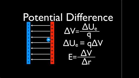
Table of Contents
What is the Potential Difference Between the Plates? A Deep Dive into Electrostatics
Understanding potential difference, often called voltage, is fundamental to comprehending electricity and its applications. This article delves into the concept of potential difference, specifically focusing on the potential difference between the plates of a capacitor, a crucial component in countless electronic devices. We'll explore the underlying physics, practical applications, and factors influencing this crucial parameter.
Potential Difference: A Foundational Concept
Before focusing on capacitor plates, let's establish a clear understanding of potential difference. In simple terms, potential difference (PD), or voltage, is the work done per unit charge in moving a charge between two points in an electric field. Imagine pushing a charged particle through an electric field. The force exerted by the field does work on the particle. The potential difference between two points represents the energy gained or lost by the particle as it moves between those points. The unit of potential difference is the volt (V), where one volt is equal to one joule per coulomb (J/C).
The Analogy of Gravitational Potential Energy
A useful analogy is gravitational potential energy. Lifting an object against gravity requires work. The higher you lift it, the more potential energy it gains. Similarly, moving a positive charge against an electric field requires work, and the charge gains electrical potential energy. The potential difference between two points is analogous to the difference in gravitational potential energy between two heights.
Capacitors and Potential Difference
A capacitor is a passive electronic component that stores electrical energy in an electric field. It consists of two conductive plates separated by an insulating material called a dielectric. When a voltage is applied across the capacitor's terminals, charges accumulate on the plates: positive charges on one plate and negative charges on the other. This charge separation creates an electric field across the dielectric.
The Role of the Dielectric
The dielectric material plays a crucial role. It doesn't allow current to flow between the plates, but it influences the strength of the electric field and the amount of charge the capacitor can store for a given voltage. Different dielectric materials have different dielectric constants, affecting the capacitance.
Capacitance: A Measure of Charge Storage
The capacitance (C) of a capacitor is a measure of its ability to store charge. It's defined as the ratio of the charge (Q) stored on each plate to the potential difference (V) between the plates:
C = Q/V
The unit of capacitance is the farad (F), where one farad represents one coulomb per volt (C/V). Capacitors typically have capacitances ranging from picofarads (pF) to farads (F), depending on their size, geometry, and dielectric material.
Factors Affecting Potential Difference Between Plates
Several factors influence the potential difference between the capacitor plates:
1. Charge on the Plates:
The most direct relationship is between the charge on the plates and the potential difference. A higher charge results in a higher potential difference. This is directly reflected in the capacitance equation: V = Q/C. If the charge (Q) increases while the capacitance (C) remains constant, the voltage (V) must increase proportionally.
2. Capacitance:
Capacitance is determined by the physical characteristics of the capacitor, namely:
-
Plate Area (A): Larger plate areas lead to higher capacitance and thus, for a given charge, a lower potential difference. A larger area allows for more charge accumulation before the voltage reaches a certain level.
-
Plate Separation (d): Smaller plate separation leads to higher capacitance. A closer proximity between the plates intensifies the electric field, enabling more charge storage at a given voltage.
-
Dielectric Constant (κ): The dielectric constant of the insulating material between the plates directly impacts capacitance. Higher dielectric constants lead to higher capacitance, and subsequently, a lower potential difference for the same charge.
The relationship between capacitance, plate area, plate separation, and dielectric constant is expressed by:
C = ε₀ * κ * A / d
Where:
ε₀is the permittivity of free space (a constant).κis the dielectric constant.Ais the area of the plates.dis the distance between the plates.
3. Applied Voltage:
When a voltage is applied across the capacitor terminals, charge flows until the potential difference between the plates equals the applied voltage. This is a key factor in determining the final potential difference. If the applied voltage increases, more charge accumulates on the plates, resulting in a higher potential difference until equilibrium is reached. This is why capacitors are frequently used to smooth out voltage fluctuations in circuits.
Practical Applications and Implications
Understanding the potential difference between capacitor plates is critical in numerous applications:
1. Energy Storage:
Capacitors store electrical energy in the electric field between their plates. The energy stored (E) is given by:
E = ½CV²
This energy can be released quickly, making capacitors essential in applications requiring short bursts of energy, such as flash photography or pulsed lasers. The potential difference directly relates to the amount of energy stored; a higher potential difference signifies greater energy storage.
2. Filtering and Smoothing:
Capacitors are widely used in power supplies and signal processing circuits to filter out unwanted high-frequency noise and smooth voltage variations. Their ability to quickly charge and discharge allows them to effectively dampen fluctuations in voltage, ensuring a stable power supply or clean signal. This capability is directly tied to the charging and discharging behavior, which is governed by the potential difference across the plates.
3. Timing Circuits:
The charging and discharging time of a capacitor in an RC circuit (resistor-capacitor circuit) determines the timing of various electronic events. This characteristic is critical in applications such as oscillators, timers, and pulse generators. The potential difference across the capacitor changes over time as it charges or discharges, allowing precise timing control.
4. Coupling and Decoupling:
Capacitors act as couplers or decouplers in circuits, blocking DC current while allowing AC signals to pass. This property is used extensively in audio circuits and other signal processing applications. The potential difference across the capacitor influences the amplitude and frequency response of the signal passing through it.
Beyond the Basics: Advanced Concepts
While we've covered the fundamental aspects, several advanced concepts further refine our understanding of potential difference between capacitor plates:
1. Dielectric Breakdown:
Applying too high a potential difference across a capacitor can lead to dielectric breakdown, where the insulating material between the plates loses its insulating properties and allows current to flow. This can permanently damage the capacitor. The dielectric strength, which is the maximum electric field the dielectric can withstand before breakdown, plays a critical role in determining the maximum operating voltage of a capacitor.
2. Non-linear Capacitors:
Some capacitors exhibit non-linear capacitance, meaning their capacitance changes with the applied voltage. This behavior can be advantageous in certain applications, but it complicates the relationship between charge, voltage, and capacitance.
3. Capacitor Charging and Discharging Dynamics:
The rate at which a capacitor charges or discharges isn't instantaneous. It depends on the capacitance and the resistance in the circuit. This dynamic behavior is crucial in understanding the performance of circuits containing capacitors, especially in time-dependent applications.
4. Parallel and Series Connections:
Connecting capacitors in parallel or series changes the overall capacitance of the circuit, consequently affecting the potential difference across each individual capacitor and the entire circuit. Understanding these configurations is essential for designing circuits with specific performance characteristics.
Conclusion: Mastering Potential Difference in Capacitors
The potential difference between the plates of a capacitor is a fundamental concept in electronics, tightly linked to charge storage, energy storage, and circuit behavior. A thorough grasp of this concept, encompassing the influence of capacitance, charge, applied voltage, and dielectric properties, is vital for anyone working with electronic circuits. Understanding the factors influencing potential difference is crucial for designing and troubleshooting electronic systems effectively. From simple RC circuits to complex power supplies, mastering this concept is essential for success in electronics engineering and related fields. By understanding the nuances presented here, you'll be better equipped to design, analyze, and troubleshoot circuits involving capacitors, enhancing your expertise in electrical engineering and related fields.
Latest Posts
Latest Posts
-
42 Feet Is How Many Meters
Apr 02, 2025
-
What Is 20 Out Of 25 As A Percentage
Apr 02, 2025
-
How Many Grams In 1 4 Ounces
Apr 02, 2025
-
How Many Centimeters Are In 20 Meters
Apr 02, 2025
-
5 1 2 Pulgadas A Centimetros
Apr 02, 2025
Related Post
Thank you for visiting our website which covers about What Is The Potential Difference Between The Plates . We hope the information provided has been useful to you. Feel free to contact us if you have any questions or need further assistance. See you next time and don't miss to bookmark.
