When Unequal Resistors Are Connected In Parallel In A Circuit
Kalali
Mar 16, 2025 · 6 min read
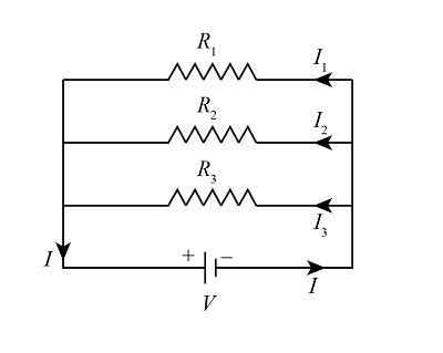
Table of Contents
When Unequal Resistors are Connected in Parallel in a Circuit
Connecting resistors in parallel is a fundamental concept in electrical circuits. While the scenario with identical resistors is straightforward, understanding the behavior of a parallel circuit with unequal resistors requires a deeper dive. This comprehensive guide will explore the intricacies of such circuits, delving into calculations, applications, and potential pitfalls.
Understanding Parallel Resistor Networks
In a parallel circuit, each resistor is connected directly to the voltage source. This means that the voltage across each resistor is the same, regardless of its resistance value. This is a key differentiator from series circuits, where the voltage is divided across each resistor. The current, however, will be different for each resistor, dictated by Ohm's Law (V = IR). The resistor with the lowest resistance will carry the most current, while the resistor with the highest resistance will carry the least.
Ohm's Law and its Crucial Role
Ohm's Law, expressed as V = IR (Voltage = Current × Resistance), forms the cornerstone of understanding parallel resistor networks. Since the voltage (V) is constant across all resistors in a parallel arrangement, the current (I) through each resistor is inversely proportional to its resistance (R). This means a smaller resistance will allow more current to flow, and vice-versa.
Calculating Total Resistance (Equivalent Resistance)
Determining the total or equivalent resistance (R<sub>eq</sub>) of a parallel network with unequal resistors is crucial for analyzing the circuit's overall behavior. Unlike series circuits where resistances simply add up, the formula for parallel resistance is more complex:
1/R<sub>eq</sub> = 1/R<sub>1</sub> + 1/R<sub>2</sub> + 1/R<sub>3</sub> + ... + 1/R<sub>n</sub>
Where:
- R<sub>eq</sub> is the equivalent resistance of the parallel combination.
- R<sub>1</sub>, R<sub>2</sub>, R<sub>3</sub>, ... R<sub>n</sub> are the individual resistances in the parallel circuit.
After calculating the sum of the reciprocals of individual resistances, remember to take the reciprocal of the result to find the equivalent resistance (R<sub>eq</sub>).
Example:
Let's consider a parallel circuit with three resistors: R<sub>1</sub> = 10Ω, R<sub>2</sub> = 20Ω, and R<sub>3</sub> = 30Ω.
1/R<sub>eq</sub> = 1/10Ω + 1/20Ω + 1/30Ω = (6 + 3 + 2) / 60Ω = 11/60Ω
R<sub>eq</sub> = 60Ω / 11 ≈ 5.45Ω
This demonstrates that the equivalent resistance in a parallel circuit is always less than the smallest individual resistance. This is because the presence of additional paths for current to flow reduces the overall resistance.
Calculating Total Current
Once the equivalent resistance is known, the total current (I<sub>T</sub>) drawn from the voltage source can be calculated using Ohm's Law:
I<sub>T</sub> = V / R<sub>eq</sub>
Where:
- I<sub>T</sub> is the total current.
- V is the voltage across the parallel combination (which is the same across each resistor).
- R<sub>eq</sub> is the equivalent resistance calculated as above.
Knowing the total current helps in analyzing the power consumption and overall performance of the circuit.
Calculating Individual Branch Currents
The current through each individual resistor (I<sub>1</sub>, I<sub>2</sub>, I<sub>3</sub>, etc.) can be determined using Ohm's Law, remembering that the voltage (V) is the same across all resistors:
- I<sub>1</sub> = V / R<sub>1</sub>
- I<sub>2</sub> = V / R<sub>2</sub>
- I<sub>3</sub> = V / R<sub>3</sub>
- ...and so on.
The sum of these individual branch currents should always equal the total current (I<sub>T</sub>). This provides a useful check on your calculations.
Applications of Parallel Resistor Networks
Parallel resistor networks are ubiquitous in electronics and electrical engineering due to their specific properties. Some key applications include:
Current Division
Parallel circuits facilitate current division, a critical aspect in many electronic designs. The current flowing through the circuit is divided among the different branches, with larger currents flowing through paths of lower resistance. This principle is utilized in various applications such as:
- Load Sharing: Distributing the load current amongst multiple components to prevent any single component from overheating or failing.
- Current Limiting: By adding resistors in parallel, a specific current limit can be established for a circuit branch.
- Sensor Networks: In sensor networks, multiple sensors might be connected in parallel to measure a single physical quantity, with each sensor contributing to the overall measurement.
Voltage Regulation
While not as directly involved as with series circuits, parallel resistors can play a role in voltage regulation through techniques like voltage dividers. However, specialized components like Zener diodes are generally preferred for more precise voltage regulation.
Improved Reliability and Redundancy
Parallel resistor circuits are commonly used in applications where redundancy is crucial. If one resistor fails (opens), the circuit continues to function, although with a slightly altered overall resistance. This is beneficial in safety-critical systems where failure of a single component cannot compromise the entire circuit.
Potential Pitfalls and Considerations
While simple in concept, working with parallel resistor networks involving unequal resistances requires careful attention to detail:
Accuracy of Calculations
The accuracy of your calculations depends heavily on the precision of the resistor values used. Small errors in resistor values can lead to significant inaccuracies in the calculated equivalent resistance and branch currents.
Power Dissipation
Each resistor dissipates power according to the formula P = I²R, where P is power, I is the current through the resistor, and R is the resistance. When dealing with unequal resistors, the power dissipation will differ across each resistor. It's crucial to select resistors with appropriate power ratings to avoid overheating and potential failure. Always ensure the power rating of each resistor is sufficient to handle the calculated power dissipation.
Tolerance and Real-World Effects
Resistors are manufactured with a certain tolerance, usually indicated as a percentage (e.g., ±5%, ±1%). This means the actual resistance value might deviate from the nominal value. When calculating the equivalent resistance in parallel, it's essential to keep this tolerance in mind, as it can affect the accuracy of the overall calculation.
Advanced Concepts and Extensions
The principles discussed above apply to simple parallel resistor networks. However, more complex circuits might involve:
- Mixed Series-Parallel Combinations: Circuits can contain both series and parallel combinations of resistors, requiring a systematic approach to solve them, often breaking down the circuit into smaller, manageable sections.
- Nonlinear Resistors: The concepts discussed above primarily pertain to linear resistors (those whose resistance remains constant regardless of the current). Nonlinear resistors, like varistors, have resistance that changes with voltage or current, requiring more sophisticated analytical techniques.
- AC Circuits: In AC circuits, the impedance (a generalization of resistance) needs to be considered, rather than just resistance, especially when dealing with capacitors and inductors in parallel with resistors.
Understanding the behavior of parallel resistor networks with unequal resistors is fundamental to circuit analysis and design. By mastering the techniques outlined above, engineers can effectively utilize the unique characteristics of these circuits in various applications, ensuring reliable and efficient electrical systems. Remember always to prioritize safety and accurate calculations to avoid potential damage or malfunction. Always double-check your calculations and consider the real-world factors such as resistor tolerance and power dissipation for a complete and accurate understanding of the circuit's behavior.
Latest Posts
Latest Posts
-
Keebler Club And Cheddar Crackers Expiration Date
Jul 10, 2025
-
In Many States Trailers With A Gvwr Of 1500
Jul 10, 2025
-
How Many Tablespoons Are In A Hidden Valley Ranch Packet
Jul 10, 2025
-
Which Is The Best Summary Of The Passage
Jul 10, 2025
-
How Many Quarts Of Soil In A Cubic Foot
Jul 10, 2025
Related Post
Thank you for visiting our website which covers about When Unequal Resistors Are Connected In Parallel In A Circuit . We hope the information provided has been useful to you. Feel free to contact us if you have any questions or need further assistance. See you next time and don't miss to bookmark.